____________________________________________________________________________________
____________________________________________________________________________________
Usage
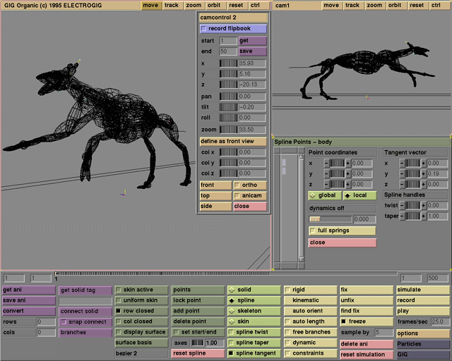
Points are selected by clicking on them or using rubber banding (dragging a loop around the points to be selected with the left mouse button). Additional points can be selected by holding down the shift-key. The icons in the selection area symbolize the spline or the skin points of the active spline. Points are not shown in solid mode or if there is no active spline. The points in the skeleton mode are the same spline points as in the spline mode.
If exactly one point has been selected, the pick area, tangent vector, angles, spline handles, and (if they are used) the dynamics and min, max entry boxes reflect the data of this point. Any changes will affect this point only. If multiple points have been selected, the entry boxes have no meaning, except for the dynamics value. However, interactive commands from the user interface affect all selected points.
Comments
Click on an empty spot in the pick area to deselect all points. Hold Shift to select multiple regions.
See also
solid, spline, skeleton, skin, close, pick area, tangent vector, global/local, angles,min,max, twist, taper, dynamics, full springs
____________________________________________________________________________________
Usage
Select one point, for example in the pick area. The point coordinate boxes will show the coordinates of the selected point. Click the entry box, the increase/decrease buttons , or the thumbwheel to change a value. The shown value depends on the editing mode (spline/skeleton for spline points, skin for skin points) and the global/local toggle.
The coordinates of the spline points are shown either in global coordinates or in the local coordinate system of the spline-skin, i.e., without any GIG transformations. The values shown for the skin points are the coordinates of the initial shape of the skin, with regard to the undeformed spline.
Comments
It is not possible to directly set the global coordinates of a skin point.
See also
pick area, spline, skeleton, skin, global/local
____________________________________________________________________________________
Usage
There are two pairs of local/global buttons. The first determines the coordinate system of the pick area and the tangent vector. Global stands for the global coordinate system of GIG; local is the coordinate system of the spline object (i.e., without GIG transformations).
The second pair of local/global buttons can be found in the angles menu. The angles menu is only available in skeleton mode in the points box.
With these buttons the user can choose between two types of rotation axes. The global rotation axes are always parallel to the x, y and z axes of the splines coordinate system (in fact, the splines local coordinate system). The direction of the local rotation axes depends on the rotations themselves. The rotations are performed one after the other: first the rotation about the y axis at the first spline point, then the rotation about the new z axis at the first spline point, then the rotation about the new x axis at the first point, and then on to the following spline points. Because of this ordering, the local x-axes are always aligned along the skeleton segments. Local angles are sometimes called yaw (for y), pitch (z), and twist (x).
Comments
Use local rotation angles to view angle constraints. If the local and global point coordinates differ, the spline object has been transformed. A transformation can be reset with the corresponding button in GIG's transformation menu.
See also
pick area, tangent vector, angles, solid, skeleton
____________________________________________________________________________________
Usage
If the dynamic toggle is switched on for the active spline, the dynamics slider can be used to set the level of dynamic animation for the selected points. It is also possible to type a value between 0 and 1 in the input box. If at least one of the points has a dynamic value larger than 0.0, a label with dynamics on appears above the input box.
The spline points and the skin points each have their own dynamic computations, so the state of the dynamics on the label and the full springs button can be different for spline/skeleton and skin editing modes. The level of dynamics lies between 0 (animated completely with key-frames) and 1 (animated completely with particle dynamics). Any number in between animates the points according to a mix of both methods.
Use the simulate button to preview dynamic behavior. Points that are completely animated with dynamics cannot be moved by click-and-drag with the mouse. Unlike most of the entry boxes in the points box, the dynamics slider can be used to change the dynamics value for several selected points at once. If more than one point is selected, the value shown is the value of the first point selected, starting at the lower left corner.
Comments
Dynamic animation is computed through particle dynamics. See the dynamic button for more details on the dynamic properties of splines and skins.
See also
dynamic, pick area, full springs, spline, skeleton, skin, simulate, Particles interface
____________________________________________________________________________________
Usage
Click the full springs button to toggle between a full and standard set of dynamic springs. A standard set of springs means that dynamic springs are constructed only between neighboring points. For spline points, springs are made between each spline point and the next and previous spline point. For skin points, springs are made at four other points along the lines displayed in skin editing mode. A full set of springs means that a spring is made from each point to every other point.
The difference between the two modes is most obvious for dynamic skins: a full set of springs causes the model to retain its volume, whereas a standard set of springs affects only the outer surface. For example, a ball-shaped skin with full springs will keep its sphere-like appearance; the same skin with standard springs might collapse to a deflated shape.
Comments
A full set of springs can become unstable if there are many skin points involved. "Unstable" here means that the movements of the dynamic points during simulation become erratic or unpredictable. Whenever there is an unstable situation this can be compensated by reducing the timestep parameter from the Particle interface.
See also
dynamic, spline, skin, dynamics, simulate
____________________________________________________________________________________
Usage
Click the close button to get rid of the points box.
Comments
All points are deselected if the points box is closed.
See also
points box, pick area
____________________________________________________________________________________
Usage
Select one spline point or one tangent vector at a spline point. The tangent vector boxes now show the coordinates of the tangent vector at the selected point. Click the increase/decrease buttons, the entry box, or the thumbwheels to change a value. The coordinates are shown in the same coordinate system as the point coordinates, i.e., in either local or global coordinates.
The tangent vector is shown as a yellow axis parallel to the spline curve if the spline tangent button is on. In this case it is also possible to change the tangent coordinates by dragging the vector on screen. The length of the tangent on screen is dependent on the axes scale value; if this value is 1.0, the vector on screen has the coordinates shown in the tangent vector boxes.
The tangent vector actually determines the shape of the spline curve through the spline point. If the auto orient option is on, the direction of the tangent vectors is computed automatically. You can still change and even animate the length of the tangent vectors.
Comments
If the auto orient option is on, the direction of the tangent vectors is computed automatically and cannot be changed. If the auto length option is on, the length of the tangent vectors is computed automatically and cannot be changed.
See also
points box, pick area, global/local, spline tangent, axes, auto orient
____________________________________________________________________________________
Usage
Select one spline point or one twist handle at a spline point. The twist entry box now shows the twist factor at the selected point. Click the increase/decrease buttons, the entry box, or the thumbwheel to change this value. The twist handle is shown as a red axis perpendicular to the spline curve if the spline twist button is on. In this case it is also possible to change the twist factor by dragging the handle on screen. The length of the twist handle is dependent on the axes scale value, but it has no relation to the spline. The twist factor determines how the skin is wrapped around the spline curve.
Comments
The shape of the skin before deformation by the spline can be changed in skin editing mode.
See also
points box, spline, spline twist, axes
____________________________________________________________________________________
Usage
Select one spline point or one taper handle at a spline point. The taper entry box now shows the taper factor at the selected point. Click the increase/decrease buttons, the entry box, or the thumbwheel to change this value. The taper handle is shown as a blue axis perpendicular to the spline curve if the spline taper button is on. In this case it is also possible to change the taper factor by dragging the handle on screen. The length of the taper handle is dependent on the axes scale value. The orientation of the taper handle has no relation to the spline. The taper factor determines how the skin is wrapped around the spline curve.
Comments
The shape of the skin before deformation by the spline can be changed in skin editing mode.
See also
points box, spline, spline taper, axes
____________________________________________________________________________________
Usage
Select one point, for example in the pick area. The angles boxes now show the angles that rotate the coordinate system at the selected point to the coordinate system at the next point. These coordinate systems can either be global or local, depending on the global/local buttons. The angles at the last spline point have no meaning.
Click the entry box, the increase/decrease buttons, or the thumb wheel to change a value. Changing an angle will cause the spline points further down the spline to rotate around the chosen axis. Global angles are shown as red (for x), yellow (for y) and blue (for z) rotation axes aligned with the splines local (!) coordinate system. This system can of course be affected by transformations in the GIG transformations menu. Similarly colored circles are displayed perpendicular to each axis to show the planes in which the points rotate.
Local angles look the same as global angles, but the rotations are performed one after the other: first the rotation around the y axis at the first spline point, then the new z axis at the first spline point, then the new x axis at the first point, and then on to the following spline points. Because of this ordering, the local x-axes are always aligned along the skeleton segments. Local angles are sometimes called yaw (for y), pitch (for z) and twist (for x).
Comments
If angle constraints are used, it is not possible to set the angles to values outside the constraint interval for that point.
See also
points box, global/local, skeleton, constraints,min,max
____________________________________________________________________________________
Usage
Select one point, for example in the pick area. The min and max boxes now show the angle constraints at the selected point. These angle constraints restrict the local angles only (because the global angles can be ambiguous). Click an entry box to change a value. If the constraints switch is on for this spline, the spline points will always be moved in a way so that the angles at each spline point do not violate their minimum and maximum values. The constrained intervals are shown as black regions on the circles that correspond to the rotation axes (shown only in skeleton editing mode with the global/local toggle on local angles).
Comments
By default the angle constraint interval is -180 to 180 degrees, that is, there are no constraints (all angles are allowed).
See also
angles, global/local, skeleton, constraints
____________________________________________________________________________________

